
Engineering guide
Stiffness calculation in gas-static bearings
Use this guide to frame what stiffness means in gas-static bearing work, which stiffness terms matter, and why a single catalogue value is not enough for a machine decision.
Controlled AURA example · AURA-PS-J15-20K
Stiffness is useful when the operating state travels with it.
This public journal-bearing case keeps geometry, clearance, supply and coefficient basis attached to the stiffness matrix, then carries the same support state into the rotor screen.
Controlled bearing state
Journal geometry and operating basis used for the public AURA stiffness result.
Kxx39.18 N/µm
Kxy+10.26 N/µm
Kyx−10.26 N/µm
Kyy39.18 N/µm
bearing statestiffness matrixrotor modelcritical-speed consequence
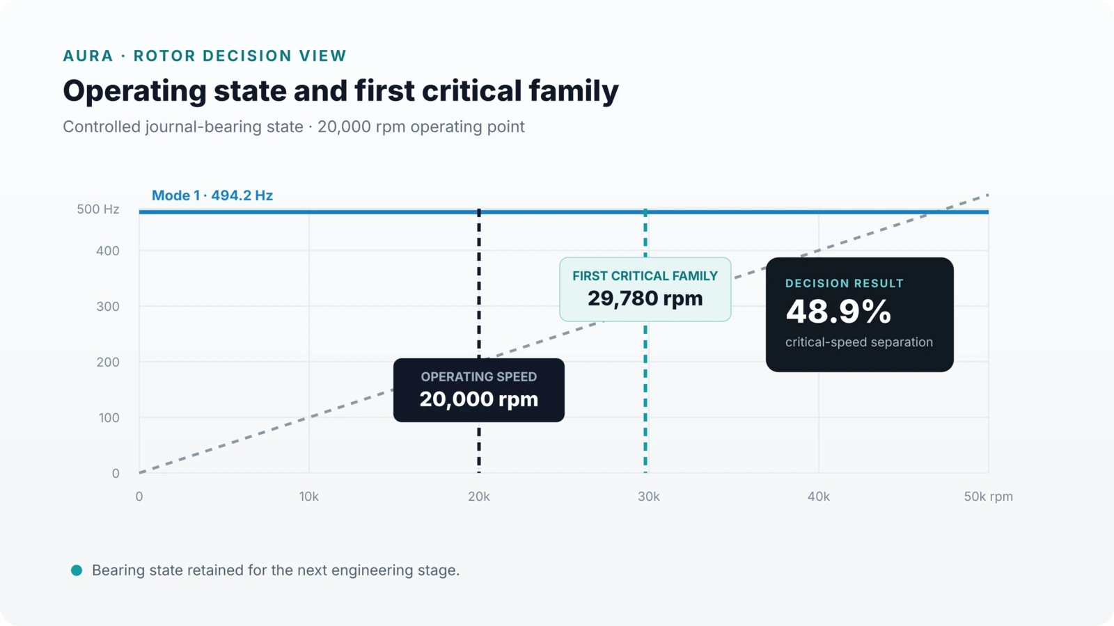
Stiffness is an operating-state result
Bearing stiffness is not a universal constant. It is the local change in gas-film reaction produced by a small change in displacement about a defined operating point. That operating point includes load, supply pressure, clearance, feed geometry and eccentric or tilted equilibrium.
In practice this means the correct question is not “what is the stiffness of this bearing?” but “what is the stiffness of this bearing at this operating state?” The answer may change materially across the load range or between centred and loaded conditions.
Which stiffness terms matter
Radial journal supports are commonly described by direct terms such as Kxx and Kyy and cross-coupled terms such as Kxy and Kyx. Thrust supports introduce axial stiffness, and conical geometries couple radial and axial components through the surface angle and support architecture.
For a complete machine decision, the bearing result must be transferred into the shaft and rotor model. The machine consequence depends not only on direct stiffness, but also on cross-coupling, support spacing, shaft flexibility and the location of the tool or process interface.
What changes stiffness most
Clearance is usually one of the strongest levers. Reducing clearance may raise direct stiffness, but it also raises tolerance sensitivity and changes leakage and contamination margin. Supply pressure and restrictor geometry determine how efficiently the source pressure is converted into a usable pressure field.
Load also matters. As the rotor shifts from the centred state, the local film geometry changes and the stiffness coefficients change with it. This is why a stiffness–load curve is often more valuable than one isolated value.
Useful outputs from a stiffness calculation
A useful engineering result does more than publish one number. It should state the controlled geometry, equilibrium state, radial and axial stiffness terms, any significant cross-coupling, the associated gas flow, and the operating pressure basis.
If the machine-level question depends on dynamic behaviour, the stiffness terms should be accompanied by damping or the declared basis for damping treatment so the result can be carried into modal, Campbell or response analysis.
How AURA uses stiffness
Within AURA, stiffness is treated as part of a support state. The state is carried forward into shaft and rotor work so that the next decision is based on critical-speed separation, response, stability or motion consequence—not on a decontextualised coefficient.
That is the practical distinction between a bearing calculation and an engineering decision: the coefficient is one result, but the machine consequence is the decision basis.
Continue the engineering chain
Related design and rotor decisions
Bearing design
Aerostatic bearing design guide
Architecture, load path, clearance, restrictors, stiffness and verification.
Open guide →Rotor consequence
Gas-bearing rotor dynamics
Carry the selected support state into critical speeds, response and stability.
Open dynamics guide →Commercial route
Architecture Screen
Apply the same chain to one machine, duty point or bearing question.
Review Architecture ScreenApply the guide to one real machine question.
Start with loads, speed, envelope, gas supply and the decision you need.