
Bearing definition
Selected support geometry, feed architecture, clearance and the state to which the result applies.
AURA Engineering Platform · method behind the work
AURA is the structured engineering platform behind the Architecture Screen. It connects process requirements, direct or inverse bearing work, bearing–shaft candidate state, rotor consequences and targeted external CFD / FE evidence without turning those tools into separate decision islands.
In business terms: one controlled decision path that shows what can proceed, what should be rejected and what evidence is still missing before commitment.
Controlled decision object
The candidate contains bearing definition, shaft-line context, operating-state identity, physical result, rotor consequence, evidence level and the next allowed decision.
Selected support geometry, feed architecture, clearance and the state to which the result applies.
Span, material, drive and working-tool interfaces remain attached to the same candidate identity.
Load, speed, gas supply, clearance and adjustment state stay explicit rather than becoming hidden assumptions.
Capacity, stiffness, flow and other calculated quantities are reported with their model and applicability boundary.
The selected support state is carried into mode-family, response and stability decisions when system-level verification is required.
The package states what is supported now, what remains unproven and the smallest next proof that can change the decision.
Connected chain
The differentiation is continuity: relationships that usually disappear between requirements, bearing tools, rotor models, external CAE and evidence records remain attached to the same candidate identity.
Decision chain · executive view
Define the machine duty and acceptance boundary.
Search feasible support states and reject weak options.
Freeze one controlled candidate basis.
Carry that state into system dynamics.
Verify only decision-critical uncertainty.
Name what is proven and what remains open.
Proceed, reject, revise or commission next proof.
Machine duty and acceptance boundary before geometry is fixed.
Candidate supports generated from required behaviour.
Support and shaft parameters remain one object.
Controlled support changes stay inside one state identity.
Frequency- and state-dependent support behaviour.
Tracked rotor branches instead of one critical number.
Weak candidates removed before expensive CAE.
Detailed evidence returned without solver lock-in.
Assumptions and evidence stay attached to the candidate.
Accepted and rejected states remain available for reuse.
Selective detailed verification
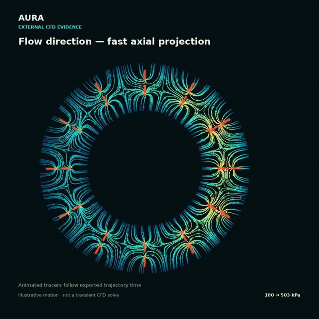
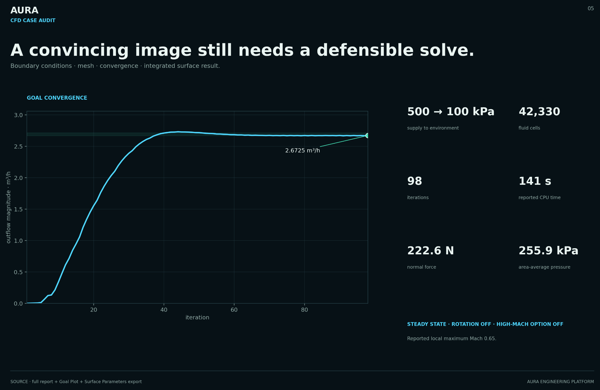
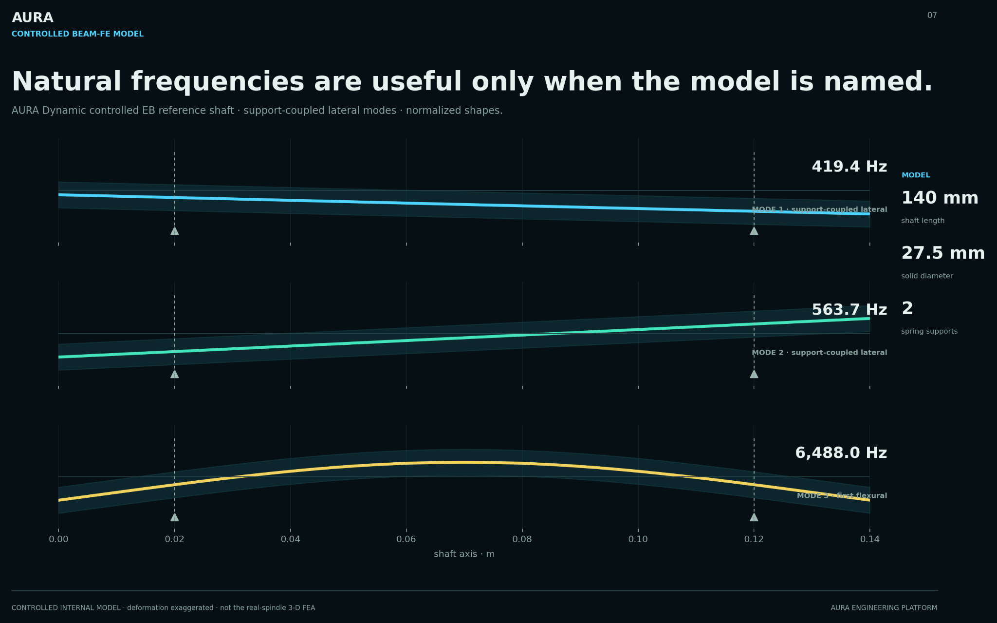
High-fidelity work begins only after analytical screening has narrowed the design space and named the exact state and discrepancy to resolve. AURA reconciles the resulting evidence; it is not presented as the CFD or FE solver.
Start with the Architecture Screen. AURA is the engineering method behind the work, not a detached software demo.