
For precision-machine OEM teams
Make a defensible gas-static spindle architecture decision before CAD freeze and supplier commitment.
Independent Architecture Screens for live custom-spindle decisions — operating envelope, viable bearing–shaft–rotor candidates, governing risks and the next proof required before commitment.
Start from the machine requirement, not a guessed bearing geometry. Screen the architecture first; commission detailed CFD, FE, prototype or supplier work only after the decision question is defined.
Start with non-confidential machine facts. A Fit Check contains no numerical design work and determines whether a scoped Architecture Screen is justified.
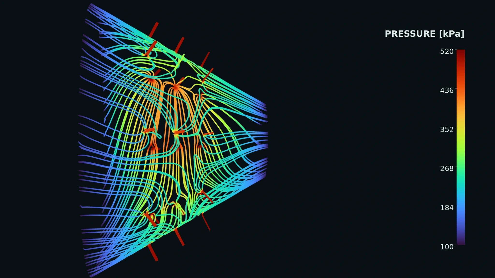
At a glance
The decision boundary before detailed engineering.
See the actual output
A bounded engineering decision, not a pile of calculations.
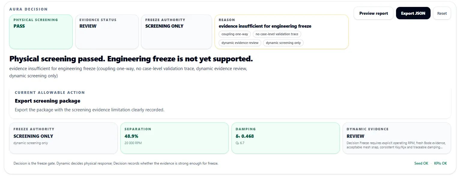
The public sample shows how one controlled case carries the operating state, support result, rotor consequence, evidence boundary and next action in one decision package.
Start here if you are evaluating the approach.
One decision, three buyer views
Start from the role carrying the commitment.
All three routes lead to the same bounded Architecture Screen. The language changes; the engineering object does not.
Protect the architecture decision.
Make the operating envelope, viable options and evidence boundary explicit before the programme commits further.
Check project fit → Spindle / Precision Motion LeadResolve the governing system constraint.
Connect bearing state, shaft line, supply, thermal behaviour and rotor consequence before freezing the brief.
Open precision-spindle path → Programme / NPI LeadProtect the freeze and proof path.
Know what is decided, what can still change and what evidence must close before RFQ, CAE or prototype work.
Open pre-RFQ checklist →Why this exists
The architecture gap appears before the supplier brief.
Recent buyer, service and integration conversations point to the same structural gap: the machine requirement sits with the OEM, while specialist gas-static spindle design capacity sits with a small number of expert teams.
An independent Architecture Screen closes that gap upstream. It does not replace the spindle supplier, CAE specialist or test laboratory; it defines the architecture and the proof question they should receive.
Flagship manufactured proof
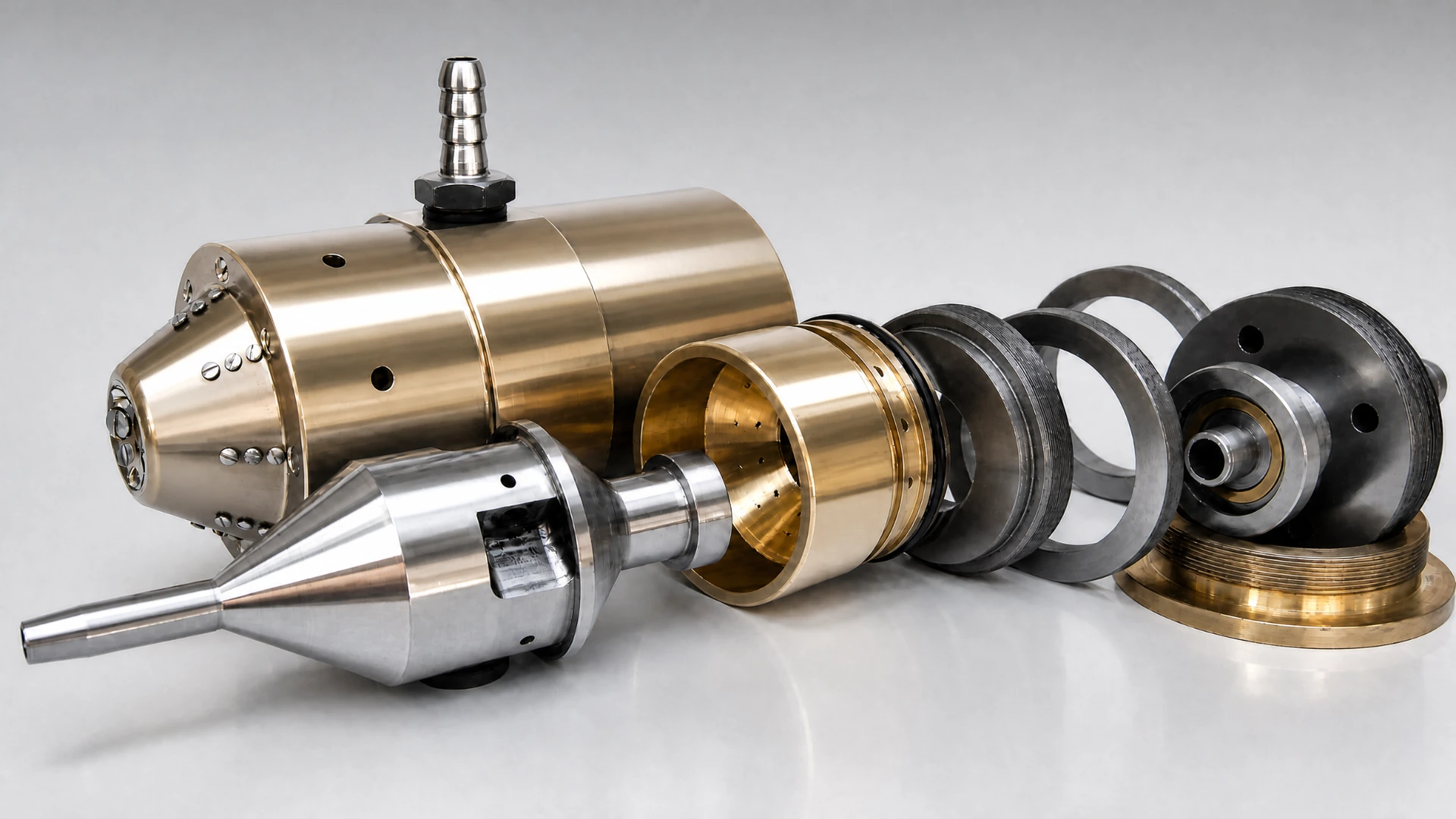
The engineering chain has been carried to real spindle hardware.
The adjustable-conical spindle case connects support architecture, gas-film calculation, rotor dynamics, production drawings, manufactured hardware and experimental / peer-reviewed evidence. It predates the current AURA product and is shown as the engineering lineage behind the method — not as a retrospective software claim.
AURA decision chain
One controlled path from requirement to engineering decision.
AURA’s differentiation is continuity. The candidate identity, assumptions and evidence authority remain attached while the work moves from fast search to system consequence, selective high fidelity and a bounded decision.
Requirements
Loads, speed, accuracy, envelope, duty and acceptance boundary before geometry is fixed.
Inverse synthesis
Generate and reject feasible gas-bearing states instead of beginning from one guessed geometry.
Bearing / shaft state
Carry the selected support state into span, material, drive and working-tool architecture.
Rotor consequence
Read critical families, orbit, response and stability against the same named operating state.
Targeted CFD / FE
Escalate only the uncertainty that can still change the architecture decision.
Evidence boundary
State exactly what the current evidence proves, what it does not prove and what proof is still missing.
Decision
Proceed, reject, revise or commission the next proof — with the reasoning preserved.
System consequence
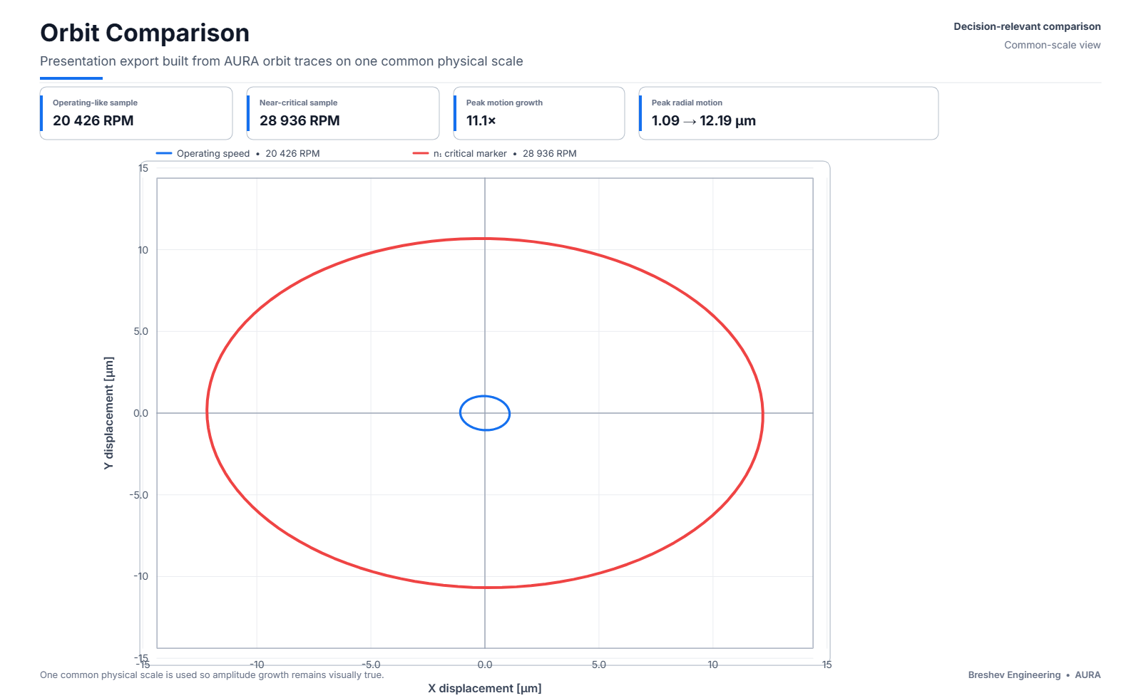
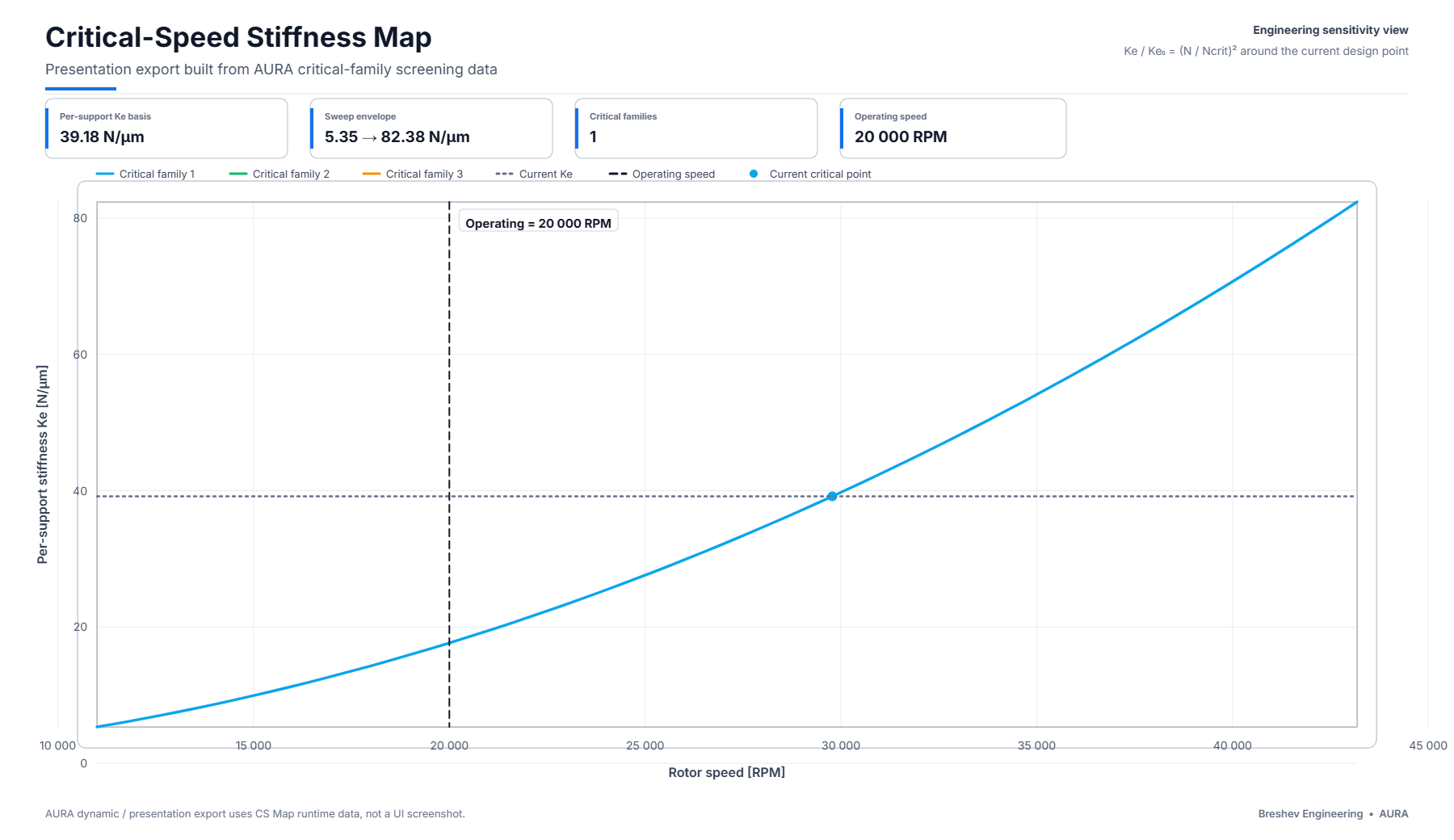
Carry the support state into rotor dynamics before judging the architecture.
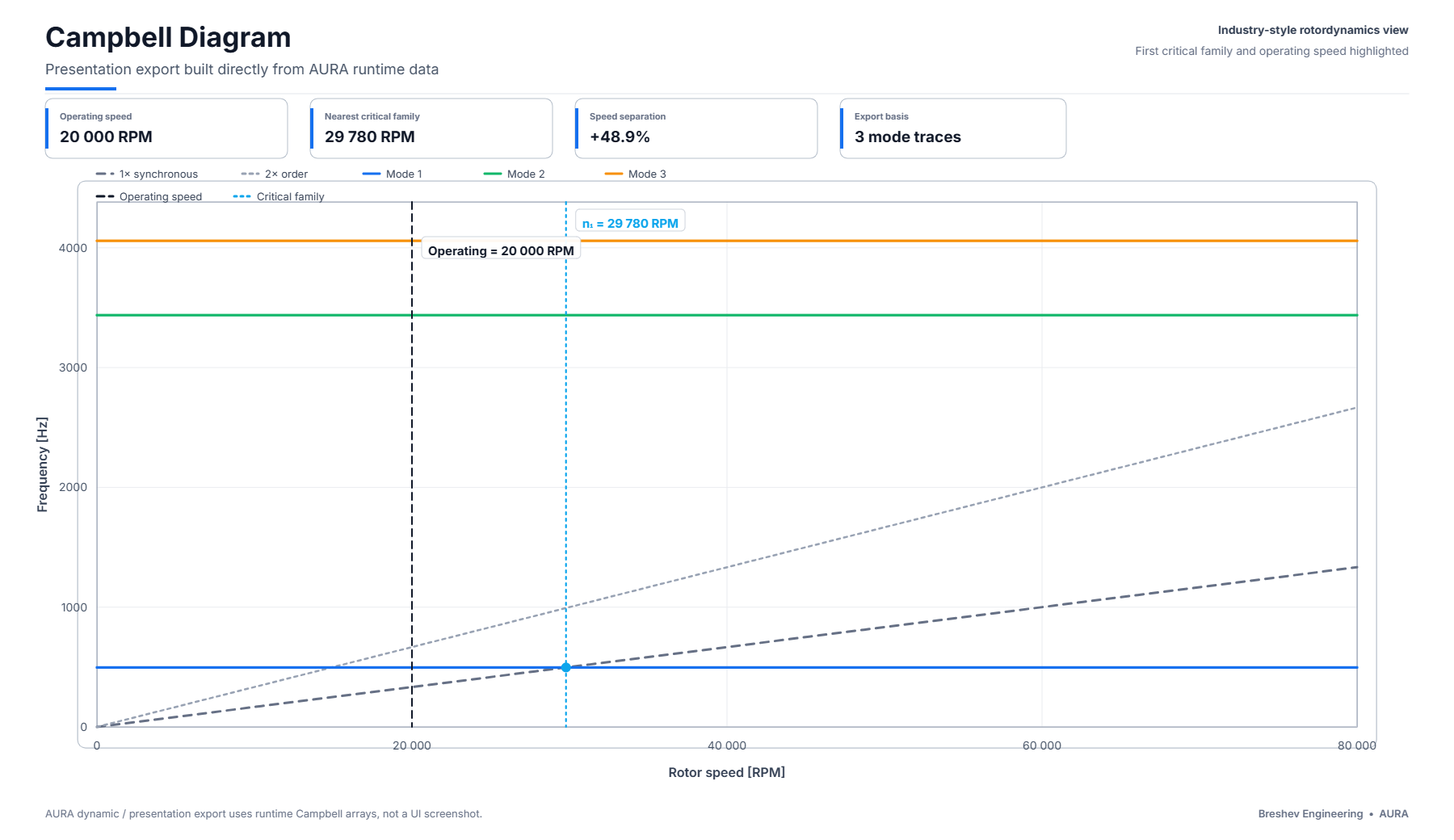
The rotor screen is read as one connected evidence set. Operating point, critical-family separation, orbit growth and stiffness sensitivity stay on the same controlled state basis, so the architecture decision is not reduced to detached plots.
This public example shows the rotor-dynamic consequence of a named support state. It supports an architecture decision; it is not a balance report, product release or acceptance certificate.
Architecture Screen deliverable
Know what can proceed, what should be rejected and what must be proved next.
The first Architecture Screen reduces architectural uncertainty: feasible options, governing state, rejected alternatives, system consequence and the smallest next proof remain in one bounded decision package.
Feasible bearing–shaft states, rejected alternatives and the reason for rejection.
Worst operating corner, support-state consequence and rotor-system margin.
Exactly what targeted CFD, FE or test must establish before the next decision.
Decision assets
Use the right working map at the right decision stage.
Three compact assets support the path from pre-RFQ architecture definition to evidence closure.
AURA advantage
Why the connected chain matters to the machine decision.
The technical chain stays connected so the team can reject weak options earlier, carry one controlled basis into rotor verification and see what evidence is still missing.
You bring a requirement, not a guessed geometry
Most workflows start from a bearing someone already drew. AURA starts from what the machine actually needs to do—load, speed, envelope and constraints—and searches for feasible bearing states that satisfy that requirement.
The bearing and the shaft are judged together
A support that looks acceptable in isolation can become unacceptable once span, tool overhang and drive architecture are included. AURA evaluates support state and shaft-line consequence as one controlled candidate, not as two calculations joined later.
One adjustable architecture can be screened across multiple controlled states
Clearance and support setting remain part of the operating-state definition, so one architecture can be checked across several duty points—and rejected where it stops being feasible—before committing to a fixed operating point.
The stiffness number only helps if you know what it means and where it applies
Catalogue, secant and local or differential stiffness are not interchangeable. AURA keeps the coefficient definition and operating state explicit, then carries the appropriate support behaviour into the rotor model.
Critical speeds are tracked as families, not one number
A single critical speed can hide how the mode moves as load, clearance and adjustment change. AURA tracks the family across controlled states so the margin is judged against the operating envelope, not one isolated point.
Weak candidates are rejected before you pay for CFD
Detailed CFD and FE are expensive per candidate. AURA narrows the field analytically first, so high-fidelity solver time is reserved for questions and candidates that can still change the decision.
CFD and FE results come back tied to the same candidate
Detailed results are reconciled against the same geometry, operating state and candidate identity that was screened, reducing translation loss between analytical work and high-fidelity tools.
Assumptions and evidence stay attached, not buried in someone’s head
Every result carries its state, assumption boundary and evidence authority, so a later engineer can see why the decision was made and what it does not prove.
Rejected options keep their rejection reason
When a candidate is rejected during the screen, the decision record keeps the reason—load, operating state, rotor consequence or evidence boundary—so the same branch does not have to be rediscovered later.
You get a decision, not a pile of plots
The output is a bounded recommendation: what can proceed, what should be rejected and what evidence is required next—not a folder of plots that still needs to be interpreted from scratch.
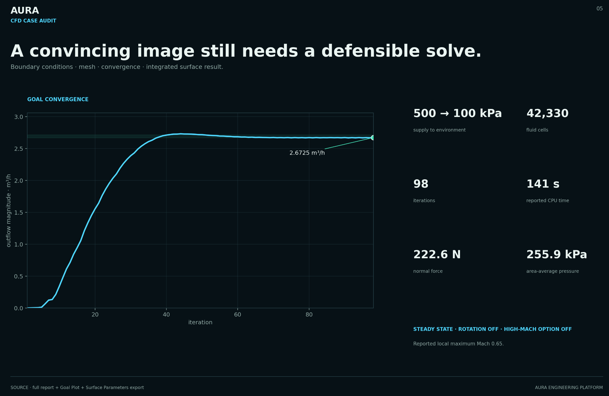
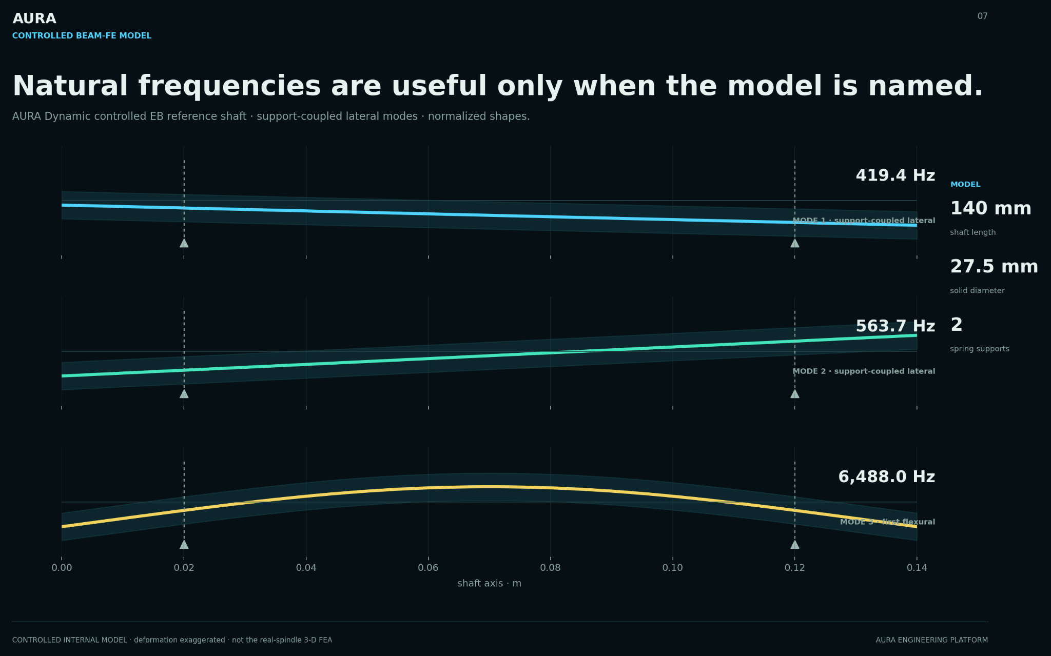
Targeted high fidelity
Detailed solvers are evidence, not decoration.
External CFD and FE are used after candidate selection, with explicit model and state identity. AURA reconciles those results back into the same engineering decision chain; it is not presented as the CFD or FE solver.
Proof library
Real machine history, manufactured hardware and bounded evidence.
Each object proves a different part of the engineering claim. Hardware does not substitute for validation; peer review does not substitute for production acceptance.
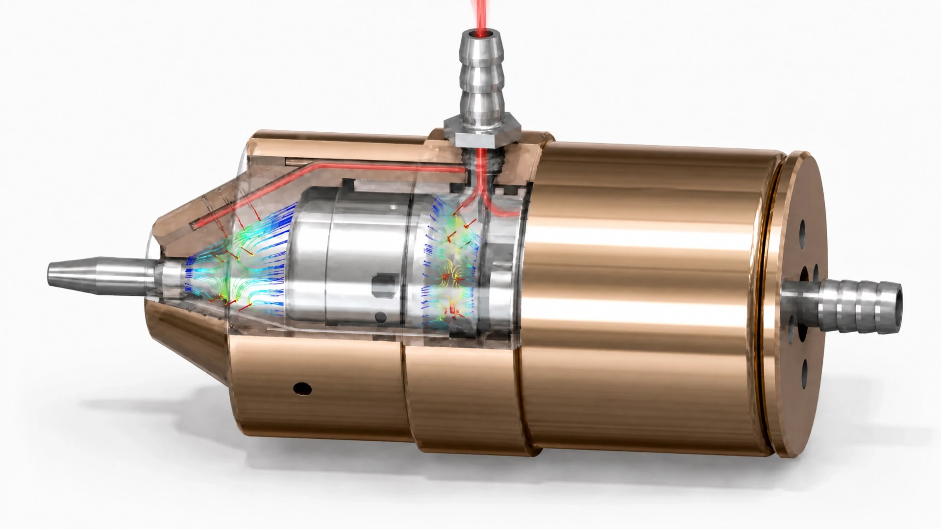
Adjustable-conical spindle
Architecture → analysis → dynamics → drawings → hardware → experimental evidence.
Open flagship case →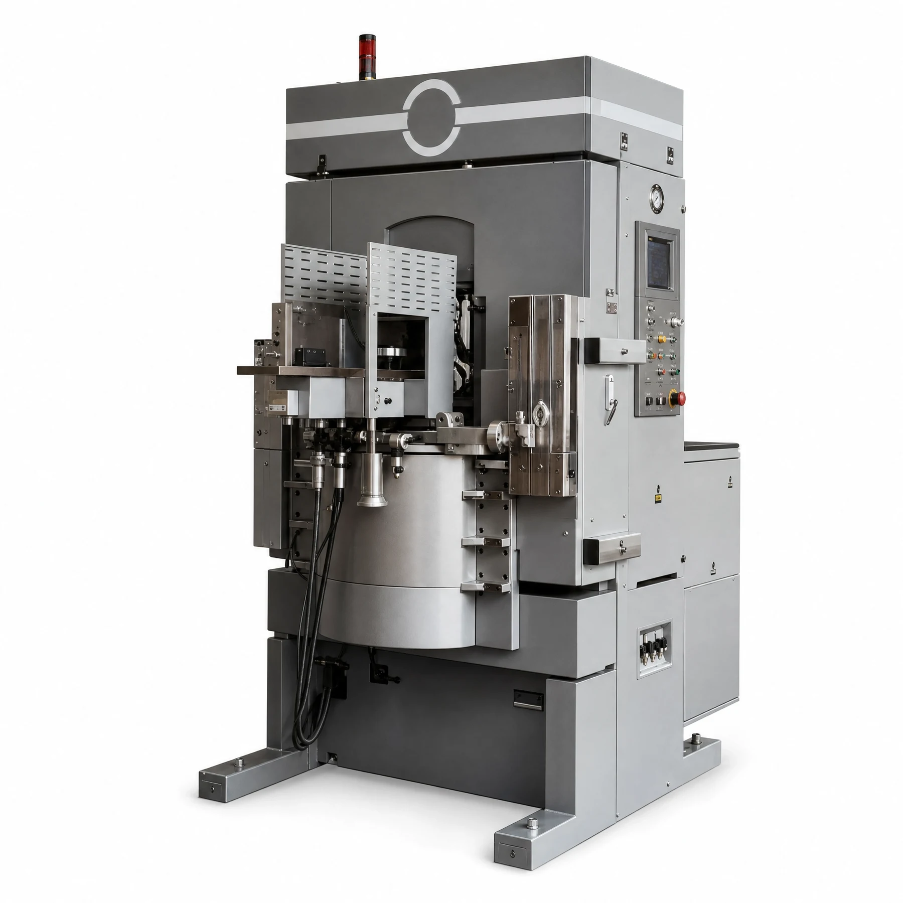
ALMAZ method chain
Operating machine, original drawings, reconstructed geometry and documented analytical basis.
Open ALMAZ case →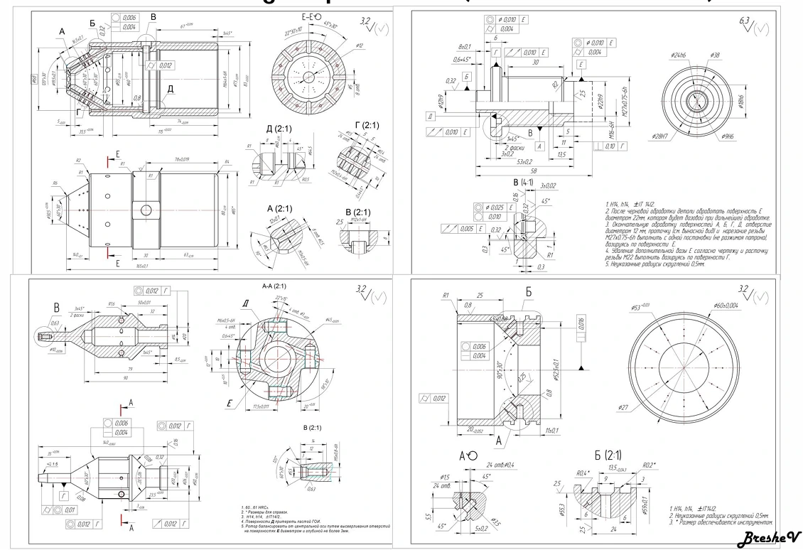
TU Berlin + Fraunhofer IPK collaboration
One key publication in a 20+ publication record connects adjustable-conical architecture and experimental verification.
Open publication →Architecture Screen output
A public example of candidate identity, governing state, evidence boundary and next engineering action.
Inspect sample package →Commercial path
Start with fit. Commission a bounded architecture decision only when the project justifies it.
The public path is deliberately narrow: qualify the live decision, then scope the smallest engineering engagement that can reduce architectural uncertainty.
Project Fit Check
Structured non-confidential intake, data-gap list and go / no-go for scoped work. No numerical design work.
Check project fit →Architecture Screen
Operating envelope, assumptions, first-order screen, sensitivities, governing risks, options and next-proof route.
Review Architecture Screen →Architecture & Evidence Package
Requirements dossier, model-tier route, supplier-independent logic, risk register and evidence / acceptance plan for the next irreversible decision.
Review deeper package →Bring one live spindle architecture decision.
Start with the machine context, operating envelope and the commitment you need to make. The Fit Check determines whether a bounded Architecture Screen is justified.