
Flagship manufactured case
From adjustable-conical bearing architecture to a manufactured spindle — and into AURA.
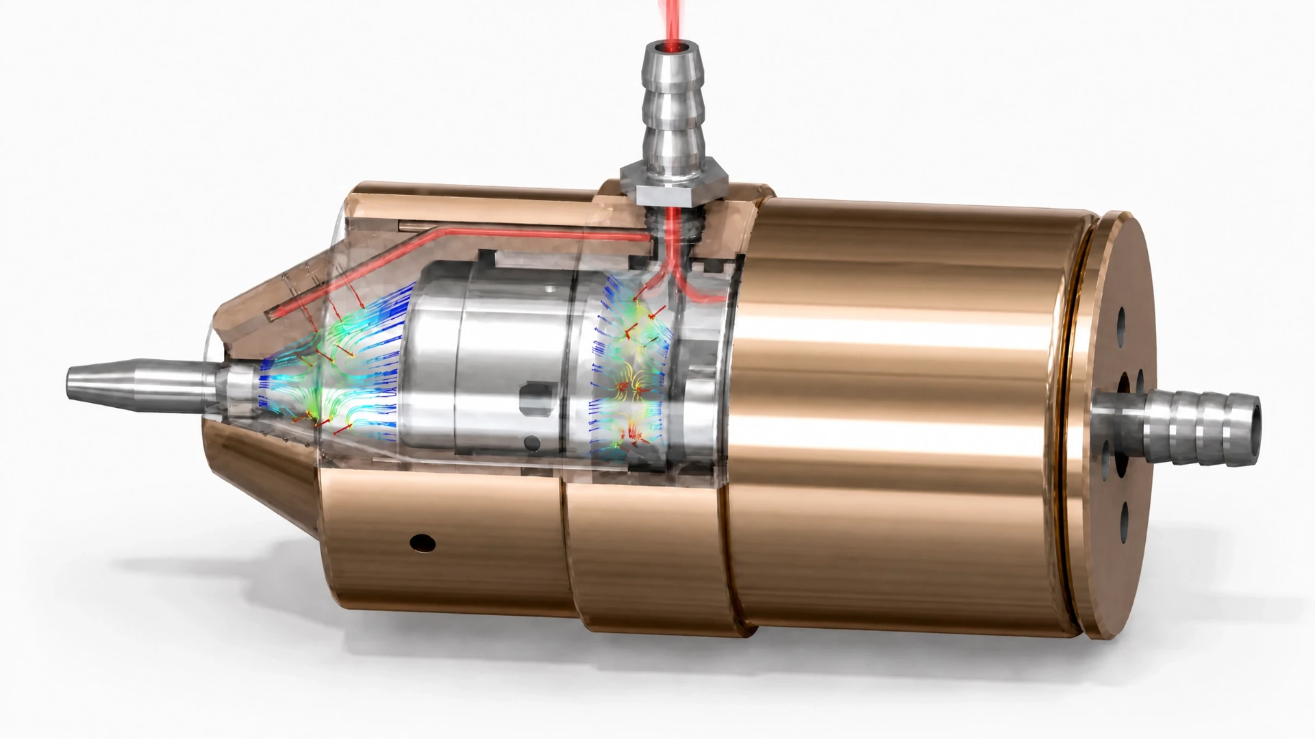
A documented adjustable-conical spindle programme is shown as an engineering realisation chain: requirement and acceptance basis, controlled support architecture, gas-film analysis, rotor-system analysis, design decision, product definition, physical hardware and experimental evidence. The work predates AURA; AURA productises the reusable method and traceability logic.
Evidence rule: every stage is shown only at the authority supported by the available record; no retrospective certification or AURA authorship is claimed.
In 60 seconds
The decision boundary before detailed engineering.
Product-realisation dossier
How a gas-static spindle moves from requirement to a controlled release decision.
A professional spindle programme is not a sequence of attractive plots. It is a controlled handoff from requirement and acceptance criteria through analysis, product definition, manufacture, assembly, inspection and test. This public case shows the records that are available and labels the release controls that are not claimed.
Requirements + acceptance
State duty, loads, speed, accuracy, air supply, interfaces and the evidence required to accept each critical requirement.
Controlled configuration
Keep geometry, clearance, supply state, assumptions and support outputs attached to one configuration identity.
Product + process definition
Translate analytical intent into toleranced geometry, manufacturing controls, inspection points, cleanliness and assembly conditions.
Measured release evidence
Separate calculation, inspection, balancing, functional test and intended-use validation; each closes a different question.
A drawing is not a test. A built spindle is not automatically validated. A publication does not replace an acceptance record.
01 · Requirements & acceptance basis
Freeze the machine question and acceptance basis before freezing bearing geometry.
The spindle is the system of interest: rotor and working interface, conical supports, pneumatic supply, packaging, operating clearances and machine interfaces must be considered together. Critical requirements should also identify how they will be accepted — by analysis, inspection, test or demonstration — before detailed definition is released.
- operating envelope: speed, radial/axial/moment loads, duty and transient states;
- precision and dynamic objectives: error motion/runout basis, vibration, critical-speed separation and thermal behaviour where relevant;
- pneumatic basis: supply pressure/range, air-quality assumption, flow envelope and loss/leakage boundaries;
- geometry and integration constraints: envelope, shaft/tool interface, mounting, adjustment and serviceability;
- acceptance logic: requirement ID, acceptance criterion, planned verification method and evidence owner.
- safety/risk basis: pneumatic energy, overspeed/rotating-part hazards and intended assembly, service and maintenance states;
02 · Architecture & operating-state definition
Define the adjustable-conical support as part of one spindle configuration.
The two conical supports, rotor geometry, clearance/adjustment state, pneumatic supply and external loading form one controlled architecture. A support result is meaningful only when the state and interfaces that produced it stay attached.
Coupled support pair
Radial and axial support behaviour are generated by one conical architecture rather than independent catalogue elements.
State definition
Clearance, supply pressure and loading remain attached to the state being analysed.
System object
The spindle architecture carries the bearing result into the shaft, rotor and machine decision.
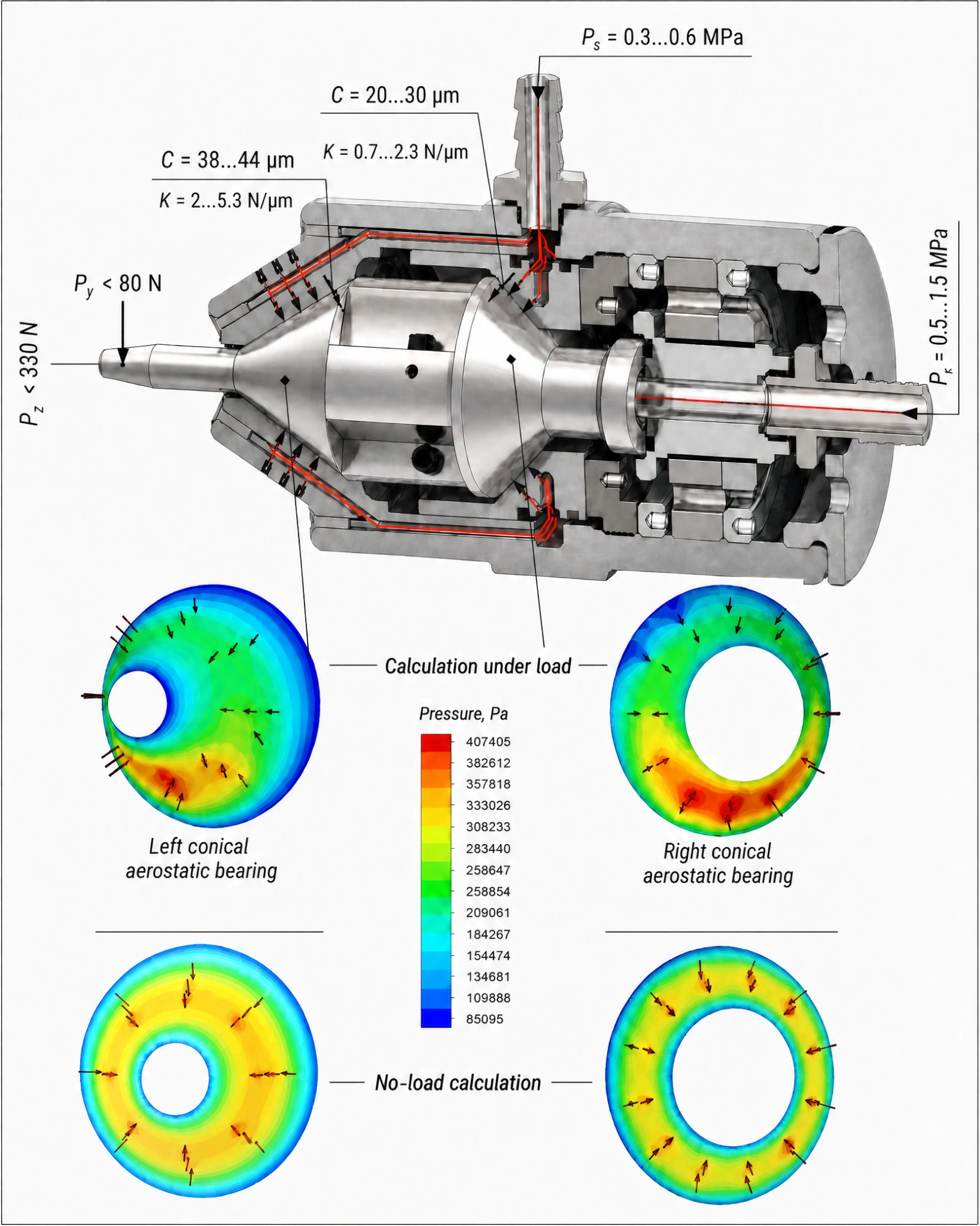
03 · Gas-film / support analysis
Resolve the gas-film state, then reduce it to support quantities the spindle model can actually use.
Pressure distribution is an intermediate model state. The engineering handoff is the integrated load/moment/flow and support behaviour associated with the same geometry, clearance, supply condition and load case. Assumptions and model scope must remain visible when those quantities pass into rotor or structural analysis.
04 · Rotor-system analysis
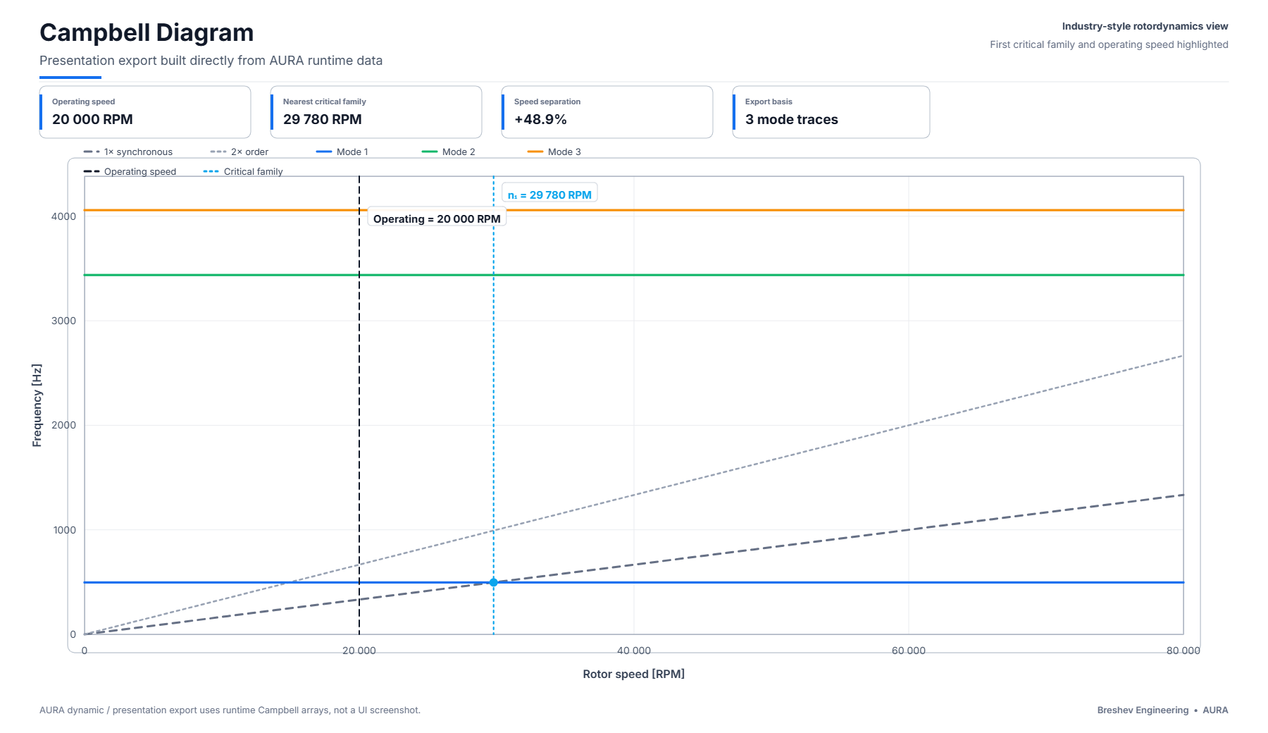
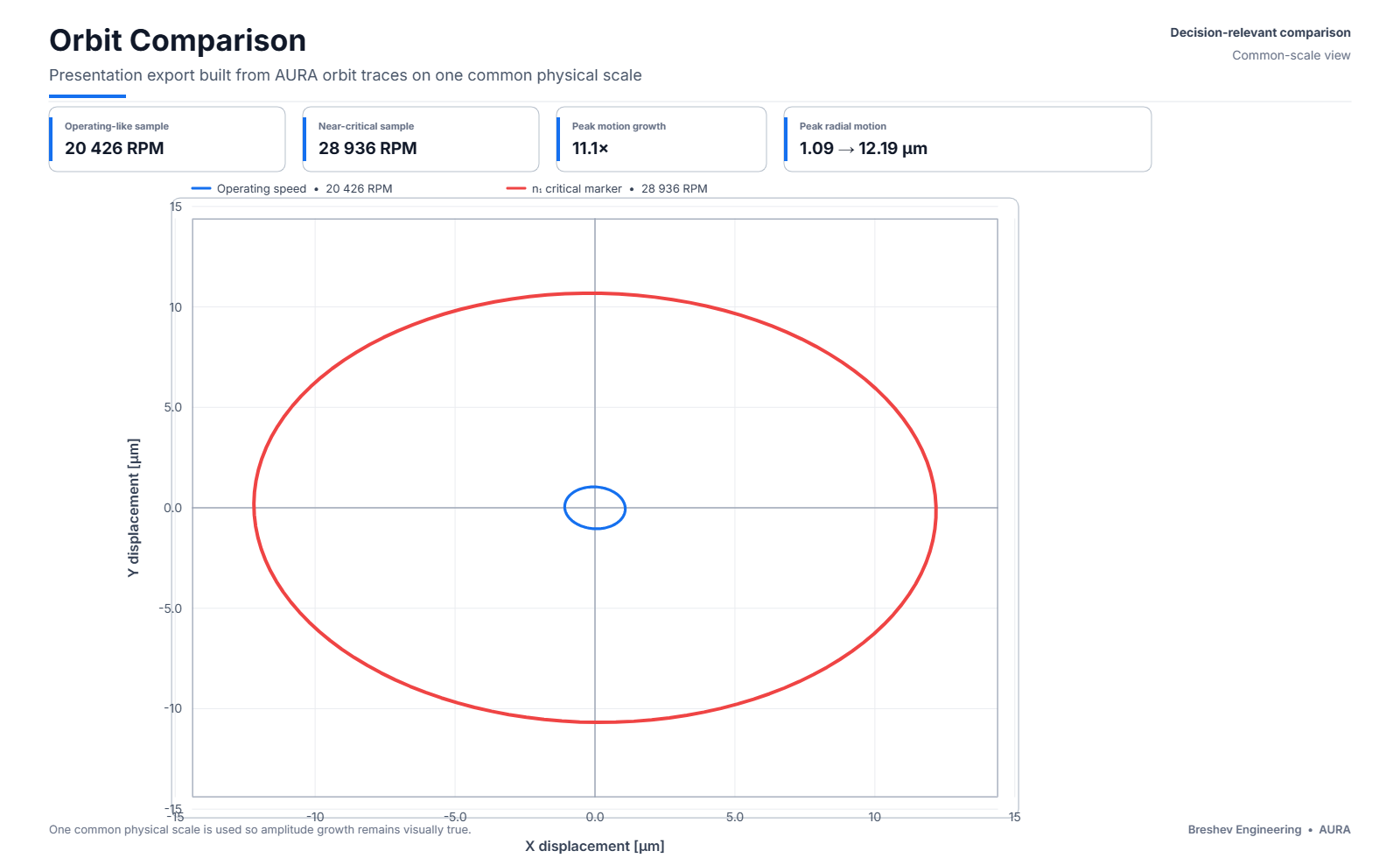
Carry the named support state into rotor dynamics before the architecture is frozen.
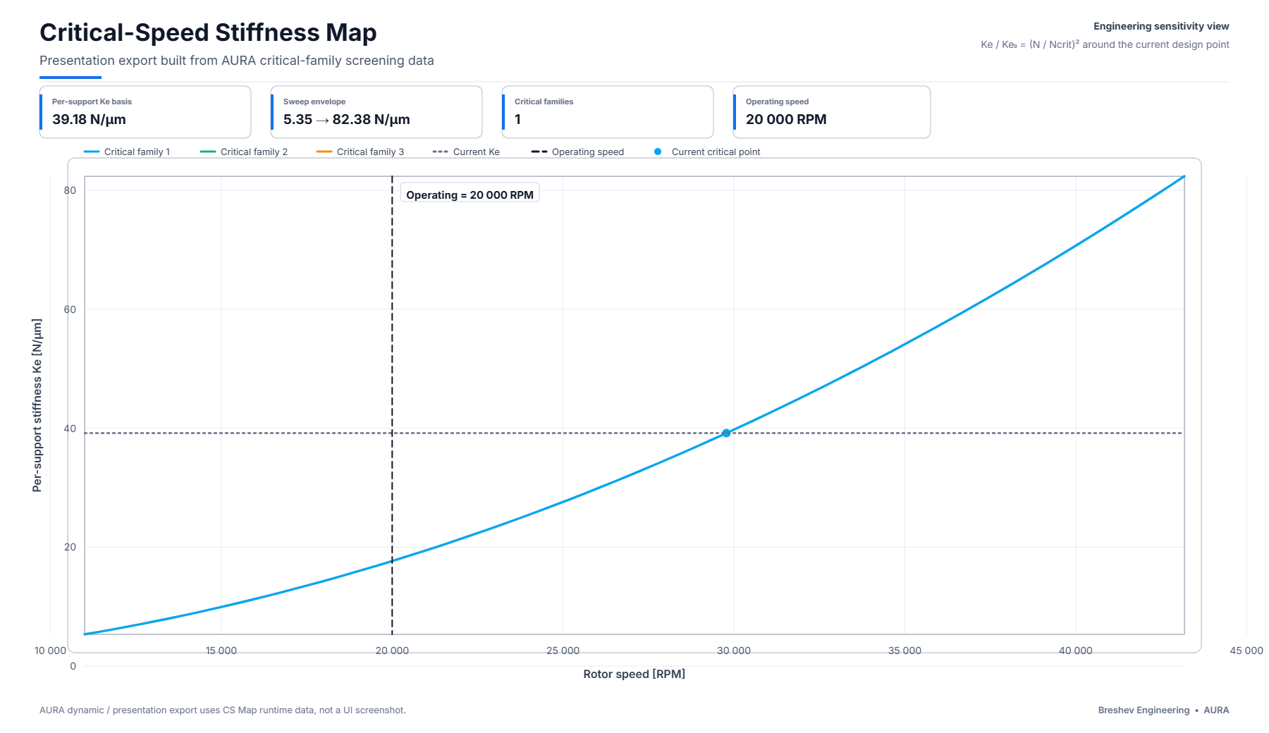
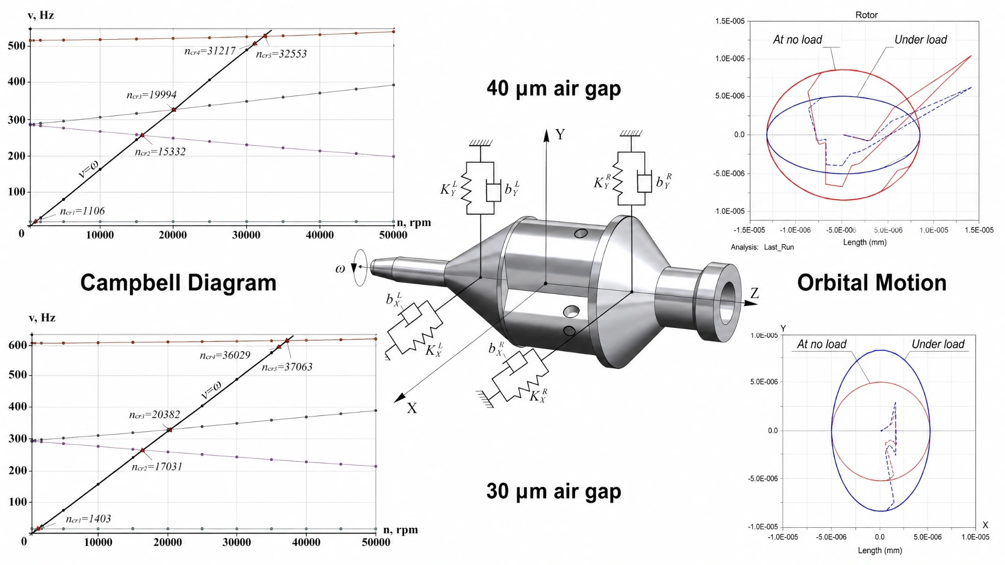
The rotor screen is read as a connected evidence set: Campbell separation, orbit behaviour and stiffness sensitivity belong to the same operating-state basis. It supports an architecture decision; it is not a balance report, spin-test record or release certificate.
05 · Architecture decision / downselect
Use system-level consequences to decide what is worth defining and manufacturing.
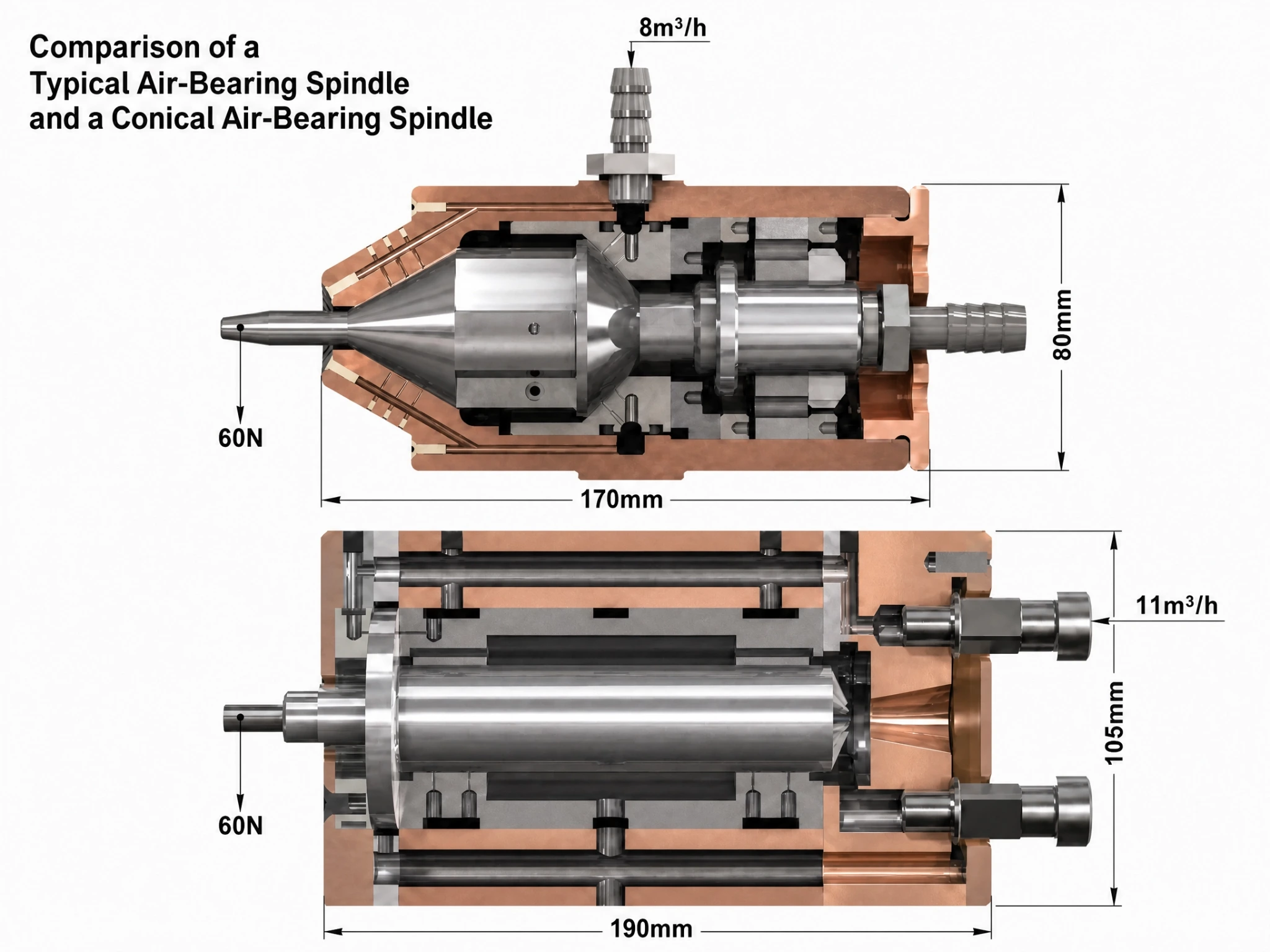
The historical comparison is design-study evidence, not a universal product claim. Its correct role is upstream of detailed release: compare architecture-level consequences, expose trade-offs and decide whether the selected concept is worth carrying into product definition.
06 · Product definition
Translate the selected architecture into controlled manufacturing definition.
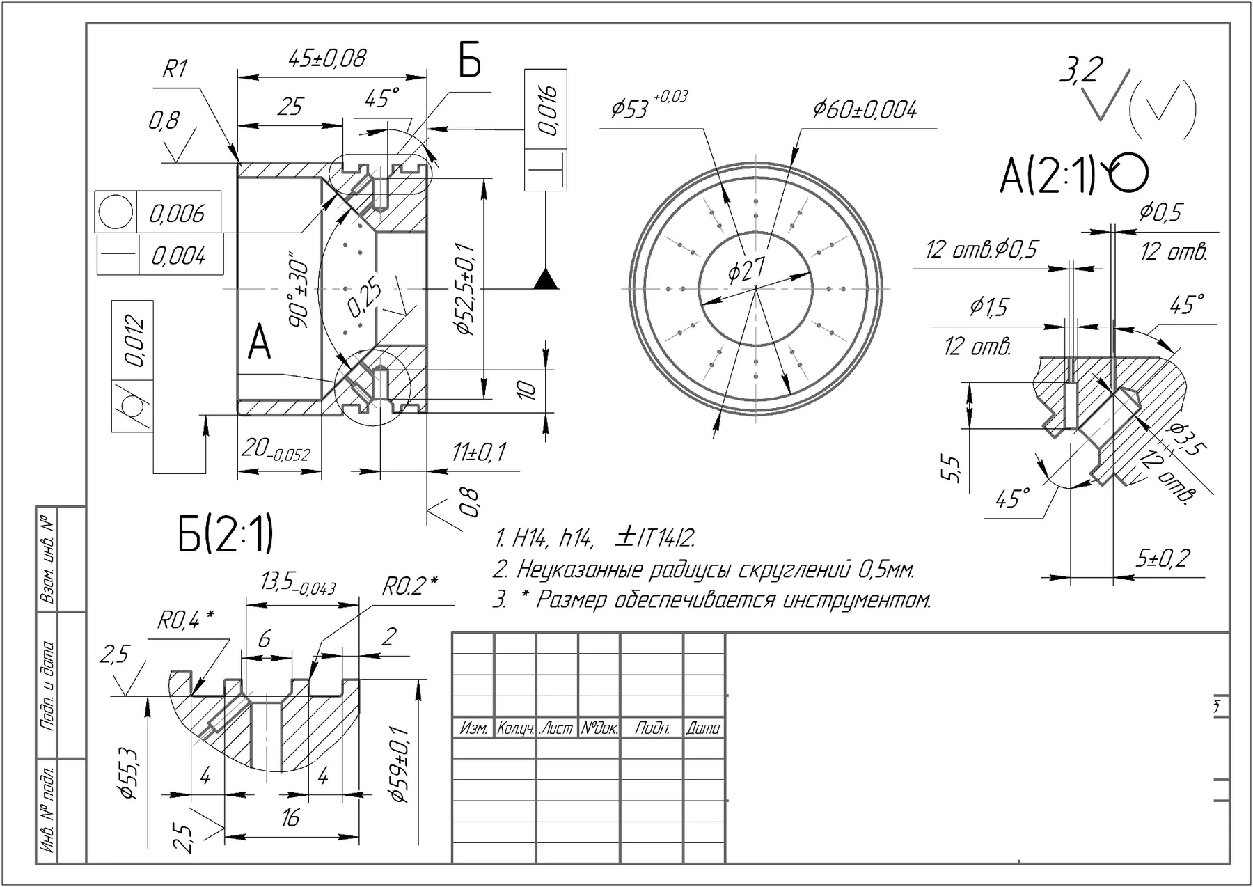
Product definition must carry design intent into dimensions, fits, geometric tolerances, surface texture, materials, feed passages, interfaces and assembly relationships. The historical drawings are shown as source records; this page does not retrospectively claim compliance with a modern GPS or drawing standard.
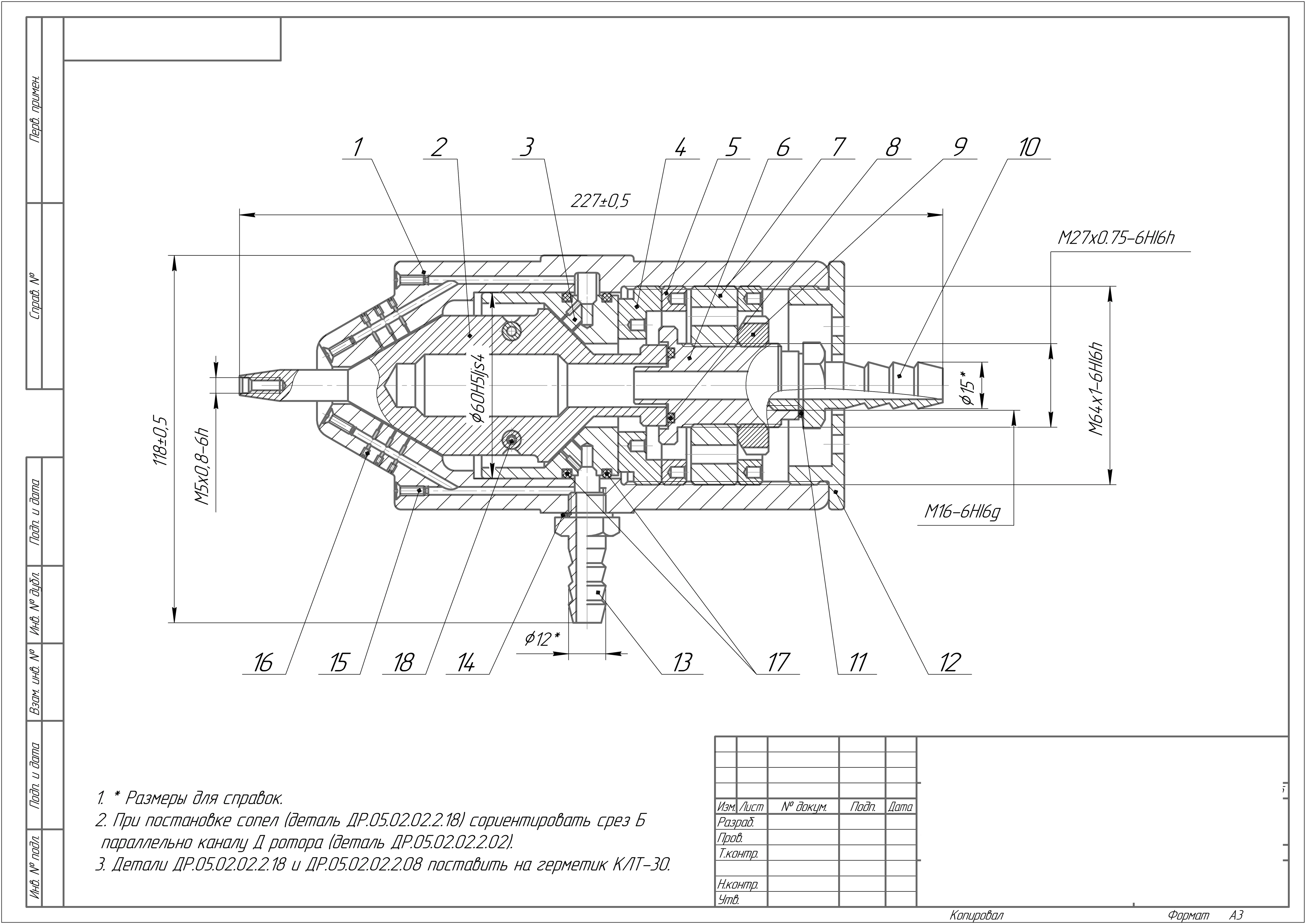
07 · Manufacturing, assembly & release controls
A production spindle needs controlled realisation records between drawings and hardware.
This public case does not claim that every historical traveller, inspection sheet, balance record or commissioning report is available here. The controls below are the professional release path that should connect product definition to an accepted spindle.
Manufacturing + inspection planning
Define operations, datums, critical characteristics, inspection stages and acceptance records before machining starts.
Machine, grind and finish controlled surfaces
Protect bearing geometry, fits, feed passages and surface condition through the chosen material and process route.
Verify dimensions, form, position and surface texture
Measure the characteristics that control clearance, conicity/coaxiality, interface alignment, surface condition and restrictor/feed geometry; use flow characterisation where geometry alone does not close the pneumatic question.
Clean parts and verify the gas-supply path
Protect small feed features and bearing surfaces from contamination; verify passages, fittings, leakage/flow behaviour and the specified compressed-air purity and pressure basis.
Assemble to a recorded configuration
Record matched parts, orientation, alignment and tightening conditions; verify and record the assembled clearance / adjustment state as a critical characteristic because it directly changes the gas film, support coefficients and rotor response.
Balance rotating parts and the assembled rotor to the defined scope
Select the balancing procedure from rigid/flexible rotor behaviour; retain residual-unbalance evidence, correction planes and any trim-balance history required by the release plan.
Controlled commissioning, speed-ramp and functional verification
Verify supply pressure/flow, lift and non-contact operation, static load/stiffness where required, vibration, temperature, speed ramps, stability and the spindle accuracy/thermal quantities defined by the acceptance plan.
Close requirements with measured evidence
Link inspection and test results to acceptance criteria, unresolved deviations and the configuration actually released.
The page shows analytical records, source product definition, manufactured hardware and published experimental work. It does not claim a complete historical manufacturing traveller, inspection dossier, balance certificate, commissioning/speed-ramp report or customer release record.
08 · Physical realisation
The documented design reached physical spindle hardware.
The manufactured spindle and principal support components demonstrate physical realisation of the selected architecture. The photograph proves build completion; it does not, by itself, prove dimensional conformance, balancing quality, dynamic acceptance or intended-use validation.
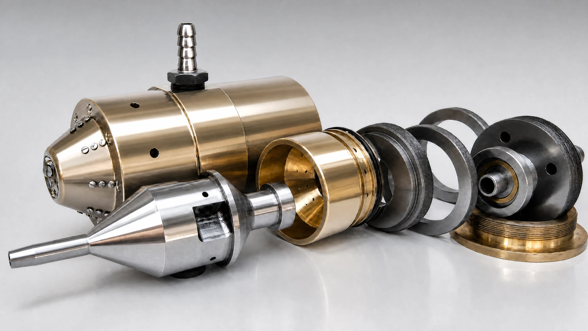
Physical evidence
Hardware confirms realisation; release still depends on controlled inspection and test.
The demonstration confirms physical realisation and operation of the architecture. Production release would additionally require the applicable inspection, balance, functional, thermal/accuracy and acceptance records defined for the intended spindle.
Open video on YouTube ↗09 · Verification, validation & release boundary
Evidence authority comes from the requirement, method and configuration — not from the visual format.
Professional release keeps analytical verification, dimensional inspection, functional testing and intended-use validation distinct but traceable to the same configuration. Peer review strengthens scientific scrutiny; it does not substitute for a product acceptance record.
Was the specified requirement satisfied?
Verification requires a defined requirement and evidence that the realized or analysed item satisfies that requirement. A calculation image alone is not sufficient to claim verification.
Does the system satisfy the intended use in its relevant context?
Validation requires context-of-use evidence. The public case documents experimental investigation and peer-reviewed work, but does not claim complete product qualification or certification.
Analysis records
Gas-film/support and rotor-system evidence for explicitly defined states.
Authority: analytical questions within model scope.Product definition
Historical component and assembly drawings.
Authority: geometry / design-definition record.Physical realisation / manufactured hardware
Manufactured hardware and demonstration are visible; a full inspection/build dossier is not claimed.
Authority: physical realisation only.Experimental evidence
Published experimental work supports the documented research claims and conditions.
Authority: measured claims within the documented test basis.Production acceptance record
Complete inspection, balance, commissioning/speed-ramp, accuracy/thermal and release matrix for a specific production unit.
Authority: would be required for production/customer release.Peer-reviewed publication
Independent scholarly review of the research contribution.
Authority: publication review; not a substitute for product acceptance.Applicable engineering discipline map
Use standards where they govern the question — never as decorative compliance badges.
These references define relevant engineering disciplines for a modern gas-static spindle programme. Applicability depends on product scope, rotor behaviour, machine integration and contractual requirements. The historical case is not retrospectively certified to them.
Define the system, acceptance basis and risk controls
ISO/IEC/IEEE 15288:2023 ↗ · ISO/IEC/IEEE 29148:2018 ↗ · ISO 12100:2010 ↗
Control geometry, fits and surface specification
Control pneumatic-system safety and supply cleanliness
Choose the balancing procedure from rotor behaviour
ISO 21940-11:2016 + Amd 1:2022 ↗ for rigid behaviour · ISO 21940-12:2016 ↗ for flexible behaviour.
Measure rotational accuracy and thermal behaviour where applicable
ISO 230-7:2015 ↗ axis-of-rotation error motion / speed-induced shifts · ISO 230-3:2020 ↗ thermal effects.
Keep requirement, definition, manufactured configuration and evidence connected
ISO 10007:2017 ↗ configuration-management guidance across the lifecycle.
10 · Configuration continuity into AURA
The reusable asset is the controlled engineering chain, not one historical spindle.
From research programme to repeatable, traceable workflow.
AURA does not retrospectively claim authorship of the historical spindle. It productises the reusable logic: requirements, defined candidate state, system consequence, targeted high-fidelity evidence and an explicit decision boundary.
Historical programme
- Machine requirement basis
- Support architecture
- Analytical calculation
- Rotor-system consequence
- Architecture decision
- Manufacturing definition
- Physical hardware
- Experimental investigation
AURA Engineering Platform
- Process requirements
- Direct calculation / inverse synthesis
- Bearing–shaft candidate identity
- Controlled support state
- Rotor-system consequence
- Targeted CFD / FE
- Evidence reconciliation
- Engineering decision
Bring a live spindle decision