
Engineering guide
Restrictor sizing in gas-static bearings
Use this guide to understand why restrictor sizing is a pressure-field design problem, not only a feed-hole diameter problem.
AURA feed-system proof
Restrictor sizing is geometry + pressure field + machine consequence.
The public journal case provides a controlled feed architecture. The manufactured adjustable-conical spindle provides a separate physical example showing how local feed-hole geometry changes the circumferential pressure distribution.
Controlled journal feed state
AURA-PS-J15-20K uses a central two-row feed architecture on an L/D = 1 journal support.
Restrictors shape the pressure field
The restrictor system controls how supply pressure enters the gas film. Diameter, count, layout and local geometry determine the resistance of the feed path and therefore the resulting pressure distribution over the support surface.
The design objective is a useful field that supports the required load, stiffness and flow, not simply the largest pressure peak at one location.
Diameter, count and location work together
Changing feed-hole diameter without considering the number of feeds or their placement can mislead the design. A smaller number of larger feeds and a larger number of smaller feeds may produce very different stiffness, flow and tolerance sensitivity even when the total area looks similar.
The layout between rows and around the circumference is part of the restrictor design, especially in conical and combined supports.
Local geometry matters
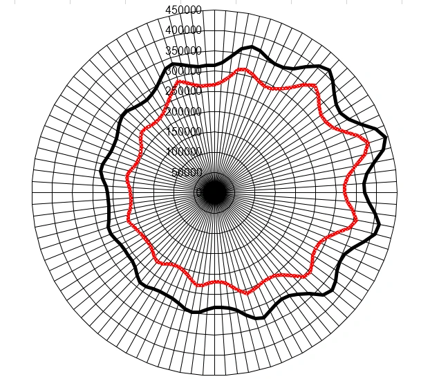
The produced adjustable conical spindle shows a direct example: the circumferential pressure distribution changes when the feed holes are countersunk. Local feed geometry changes how the gas enters the film and how the pressure equalises between rows.
This is why restrictor design should include the entrance geometry, not just the through diameter.
What the calculation should return
A useful sizing result should identify the chosen diameter and count, the feed arrangement, expected flow, equilibrium pressure field and the load/stiffness consequences at the defined operating state.
When the pressure ratio is high enough for choked flow behaviour, the calculation basis should state how that was treated.
From analytical selection to verification
Analytical screening is an efficient way to reduce the candidate space and find promising restrictor configurations. CFD or test can then be used on the selected geometry to inspect local field behaviour in more detail.
That sequence uses each tool for the question it answers best and avoids spending high-fidelity effort on weak candidates.
Continue the engineering chain
Related design and rotor decisions
Bearing design
Aerostatic bearing design guide
Architecture, load path, clearance, restrictors, stiffness and verification.
Open guide →Rotor consequence
Gas-bearing rotor dynamics
Carry the selected support state into critical speeds, response and stability.
Open dynamics guide →Commercial route
Architecture Screen
Apply the same chain to one machine, duty point or bearing question.
Review Architecture ScreenApply the guide to one real machine question.
Start with loads, speed, envelope, gas supply and the decision you need.