
Engineering guide
Clearance and tolerances in gas-static bearings
Use this guide to connect nominal clearance to real manufacturing and assembly decisions, rather than treating clearance as a free numerical input.
Public AURA proof · two controlled examples
Keep calculated clearance and manufacturing definition separate—but traceable.
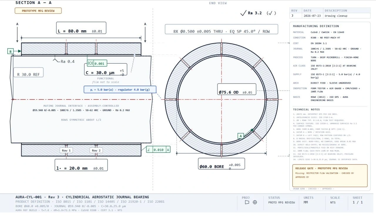
The numerical rotor case and the production-oriented drawing are different public examples. Both use a 30 µm functional clearance, but they are not the same geometry and are not presented as one combined case.
Example A · controlled rotor case
AURA-PS-J15-20K keeps the nominal support state attached to the rotor decision.
Clearance is functional, not decorative
The gas-film clearance sets the local geometry in which the pressure field is generated. It therefore influences load capacity, stiffness, flow, thermal sensitivity, contamination tolerance and the minimum remaining margin before contact.
Because of that, the functional clearance should be stated with the bearing definition and not inferred loosely from nominal dimensions.
From nominal size to real interface
The effective operating clearance depends on journal size, bore size, form error, waviness, roundness, straightness, surface finish, thermal state and assembly condition. A nominal diameter callout alone does not define the gas film.
Production-oriented engineering must therefore connect the calculated clearance to tolerances, measurement practice and the controlled assembly basis.
Why tighter is not always better
A tighter clearance may increase stiffness and reduce leakage, but it can also reduce tolerance margin and make the support more sensitive to thermal growth, contamination, handling damage or installation error.
The right engineering target is a usable margin with a credible manufacturing route—not the smallest number that still converges in calculation.
Tolerance strategy
A good tolerance strategy separates what is functional from what is merely dimensional. Functional interfaces deserve explicit control: bore and journal sizes, roundness, coaxiality, local feed geometry and inspection basis.
Where the machine will be built more than once, the drawing should also record what is assembly-controlled, what is paired, and what must be checked before prototype manufacture or review.
Link to the next proof step
Clearance and tolerance choices should feed directly into the next proof route. For some concepts that means a production-oriented bearing definition. For others it means CFD on the selected geometry, supplier review of capability, or prototype inspection and test.
The key is that clearance remains traceable from calculation through manufacture and review.
Continue the engineering chain
Related design and rotor decisions
Bearing design
Aerostatic bearing design guide
Architecture, load path, clearance, restrictors, stiffness and verification.
Open guide →Rotor consequence
Gas-bearing rotor dynamics
Carry the selected support state into critical speeds, response and stability.
Open dynamics guide →Commercial route
Architecture Screen
Apply the same chain to one machine, duty point or bearing question.
Review Architecture ScreenApply the guide to one real machine question.
Start with loads, speed, envelope, gas supply and the decision you need.